
FJD1
Circuit Design
This µ-amp began as a hand-drawn analog circuit and was rebuilt in KiCad as a compact, through-hole printed circuit board. Explore both the original and updated boards in 3D, then continue below for the circuit description, response charts, specifications, testimonial, frequently asked questions, and ordering information.
This browser could not start the updated VRML viewer.
/circuits/shapes3D/. Value-specific 0Ω, 100kΩ, and 120kΩ resistor models now show
their color bands. Two-sided rendering prevents cutaway faces, and the same Isometric, Top, Bottom,
Reset, and Auto-rotate controls are provided as on the original model.
µ-Amp: Boost, Bite, and Musical Compression
A compact, battery-powered onboard preamp designed for magnetic pickups. It can run clean as a boost, or push into a guitarist-friendly “edge” with a unique gain/feedback control that players describe as lively and touch-responsive.
What It Does
- Clean boost to wake up long cable runs, pedal chains, or a lazy amp input.
- Musical drive that can feel like “sweet grit” rather than harsh fuzz.
- Touch compression that responds to pick attack—great for lead lines and sustained chords.
- True bypass via DPDT switch—straight pickup-to-jack when off.
Why It Feels Different
The gain control is not a typical “volume knob.” The input is injected at the pot’s wiper while the pot also participates in the feedback path. Turning it changes more than gain: it changes loop behavior, impedance at the summing node, and how the op-amp approaches its limits, often perceived as “alive” and expressive.
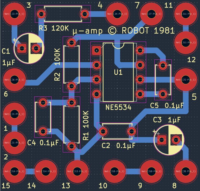 Circuit board.
How It’s Wired (Plain English)
Signal Path
- Pickup input → series resistor (about 120kΩ) → 1µF coupling capacitor.
- That signal goes to the wiper of a 500k potentiometer.
- The pot participates in feedback between the op-amp output and the inverting input (pin 2).
- Output is AC-coupled through a 1µF capacitor to the output jack.
- A stereo jack can disconnect the battery negative when unplugged.
Bias and “Feel”
- Non-inverting input (pin 3) is biased at mid-supply with a 100k/100k divider.
- A 0.1µF cap decouples that bias node to ground for stability.
- Output includes a 0.1µF cap to ground (a strong contributor to the circuit’s character).
- Optional small compensation cap at the op-amp comp pin may be present (value depends on build).
Specifications (Typical / Adjustable)
| Power | 9V battery (optional 18V with two batteries, more headroom / cleaner boost) |
| Bypass | DPDT true bypass (pickup straight to output when off) |
| Operational amplifier | NE5534 introduced by Signetics in 1979 |
| Input | Magnetic pickup (passive) |
| Gain Range | Approx. 0× to ~4.2× (about +12 dB), depending on pot wiring and component tolerances |
| Output | AC-coupled to output jack; stereo jack can act as battery disconnect |
| Cable Compatibility | Designed to comfortably drive typical 10–20 ft guitar cables when engaged |
These are practical, musician-focused specs. Exact response depends on pickup, cable, amp input, and control position.
Installation Notes (Tech-Friendly)
- Keep leads short and routing tidy—this circuit can be sensitive to layout because of capacitive loading.
- Recommended: add a small series resistor on the op-amp output (e.g., 47–220Ω) if you want extra stability without losing character.
- Use a stereo output jack for battery negative switching (battery disconnect on unplug).
Testimonial

The µ-amp is unique for some of the material aspects, but mostly the 5534.
The slew rate of the 5534 was 48k which allowed full frequency headroom in the audio range. The electrolytic to ground were filters for squeal and noise.
I must admit there is perceived compression with increased volume, but no limiting roll off like real compressors.
The audio is clean replication of the original pickups, behaving with the tonal and harmonic characters of a Les Paul 1970 windings.
No distorted clipping at all when the amp was in clean mode. I’ve experienced only one pedal with these characteristics, but it was a clipping compressing OD with many tone controlling aspects with many choices, and that’s not always good. The µ-amp is mono dimensional: hit the switch+ volume on 10! I played hundreds of hours with our preamp and it is a fond memory.
Tube amps loved the input voltage and capacitance with a 20' cable!
Ordering Information — Send Check To
Delphi O.E.M. Co5348 216th Ave SW
Centralia, WA 98531