VRML Tutorial
Unit 1 Hello Box?
Unit 2 The Box Again!
Unit 3 Two Blue Boxes
Unit 4 Cones and Cylinders and Spheres Oh My!
Unit 5 Clickable Link
Unit 6 ViewPoints and Background
Unit 7 JavaScript version of Demo 3
Unit 8 Extrusion and LOD

If you need professional help, send me an e-mail describing your needs and how to best contact you.Sincerely,
F. Davies
fjdavies@yahoo.com
(360) 352-0242
ICQ 43536012
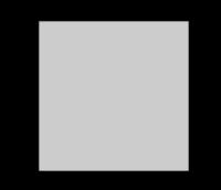
Demo 1 Hello Box?
Click here to view Demo 1 in a new window
I am assuming you have VRMLpad and would like to try it out. Open it up. You will see a 'new untitled document' with:#VRML V2.0 utf8
As the first line. (You can write this in any text editor. Save it as demo001.wrl and send it to notepad to edit it.) EVERY vrml page/document MUST have EXACTLY that line at the VERY top. ALWAYS. Or it won't work. Ever. And the capital letters and small letters can't even be changed as it is 'case sensitive'. But from after that line, you can type a "#" and it is a 'comment' till the end of the line. This could be your next line, a line which does absolutely nothing by the way:#first program: demo001.wrl
VRML uses 'nodes'. That is what they call them, and they are like electronic circuits. They can be connected. Reused. Named. They can take in some data. They can put out some data. They 'do stuff'. Nodes can contain other nodes, thus called parent and child to each other. Here is the way you can make sure the user's headlight is turned on:NavigationInfo {headlight TRUE }
That was the NavigationInfo node, and in the curly braces the headlight was set to TRUE to make up for not having any lights in this scene. Next you need a shape node which also has a pair of curly braces and some stuff in them. In shape nodes you need to have a geometry and appearance nodes both. In the Appearance node is the material node and it is empty just like the Box. (Nothing is in the curly braces so it is the default size box and the default color of material. Notice the use of upper and lower case letters, they must be exactly as below:Shape { geometry Box {} appearance Appearance { material Material {} } }
And that is all you need to make a box in VRML. Save it as demo001.wrl and then find it and click to open it in explorer, (or dragging it into explorer works too.) Here is the complete demo001.wrl file.#VRML V2.0 utf8 #first program: demo001.wrl NavigationInfo {headlight TRUE } Shape { geometry Box {} appearance Appearance { material Material {} } }
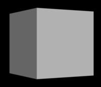
Demo 2 The Box Again!
Click here to view Demo 2 in a new window
VRML has only a few built in shapes: Box, Cone, Cylinder, Sphere, IndexedFaceSet etc. (VRML pad will help you write code. RIGHT CLICK and a menu will pop up with the items to choose which you can use. Do it with the cursor positioned in the middle of braces and you get choices to put there. Also try ctrl space to complete.) Highlight the word 'Material' and right click and choose 'edit Material' and a window comes up to let you pick out colors. This will fill in several things at once, all inside the Material node. Colors are represented with three numbers for Red Green and Blue with one (1) being the most and zero being no color. Lime green is: 0 1 0, black is: 0 0 0, yellow is: 1 1 0, white is 1 1 1, gray is: .5 .5 .5 (all the same, like black and white are all the same!) The X-axis goes to the right, the Y-axis is up, the Z-axis is coming toward you with minus-Z going away toward the horizon line in front of you. Angles are all in radians (2 times pi is all the way around so half way is 3.141 radians and what you call 90 degrees is written simply as 1.57 radians, but you don't need the word 'radians' just the number.) The angles are measured using the 'right hand thumb rule'; 'with the thumb pointing along the axis, the fingers curl and point in the direction of spin. Minus goes the other way.) Angles also need to say which axis to turn on so they actually are four numbers in one (4-vectors.) The first is X the next is Y the third is Z and the fourth is the actual angle. Make the axis you want to spin on a one (1) and the other two zeros. This would turn about 90-degrees: 0 1 0 1.57 So this would be 30-degrees:rotation 0 1 0 0.52
To do this to your Box, we need to add another node which encloses everything we have in Shape. Shape will be a child of this new transform node and the final code should look like:#VRML V2.0 utf8 #second program: demo002.wrl NavigationInfo {headlight TRUE } Transform { rotation 0 1 0 0.52 children [ Shape { geometry Box {} appearance Appearance { material Material {} } } ] }
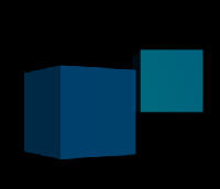
Demo 3 Two Blue Boxes
Click here to view Demo 3 in a new window
Notice how I indent? It helps keep things straight to indent like you were writing an outline. If you experiment, change the version number whenever you start a new experiment, so you always have some working versions. I save-as with a new number every time I get things working, and start doing the next experiment with this new number. Keep changes very small and then save, and check the parsed output in explorer. Repeat many times. Version all which work and start on the next experiment. Right click to see the possibilities and then select and enter. Remember to put the mouse in the braces and do it too! Most errors will be due to the braces not being right so watch where they start and stop. You can name something and use it again, with a transform to make sure it is not on top of something else. Here is a more complete example with a bit of color added too:#VRML V2.0 utf8 NavigationInfo {headlight TRUE } #third program: demo003.wrl Transform { rotation 0 1 0 0.52 children [ DEF boxthing01 Shape { geometry Box {} appearance Appearance { material Material { diffuseColor 0 .48 .8 specularColor 0 .3 .5 emissiveColor 0 .09 .15 ambientIntensity 0 transparency .5 } } } ] } Transform { translation 3 1 -4 children [ USE boxthing01 ] }
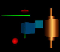
Demo 4 Cones And Cylinders And Spheres, Oh My!
Click here to view Demo 4 in a new window
Well I hope that gives you a start. I received a letter today from a student in Indonesia and am sending a copy of this to her so she can get a start on building a virtual hospital tour. Boxes make great walls, floors, ceilings, you just need to size them and color them right. A lot of the furniture and fixtures etc. can be made from just a few simple lines of code like 4 cylinders for a table legs and a (flat, and transparent) box for the glass table top. Change it just a little and you have a counter or bookshelf. Add a small sphere on the ends of the legs or use cones instead of cylinders to add variations. Make them different colors and sizes. THINK IN METERS! A one (1) means one meter. Sure you can scale to any size, but try to think this way and you will be closer to correct dimensions to start with and the scaling will not be so severe. Spend a half hour a day writing code. Practice writing some code most every day or you will find your programming skills getting weaker instead of stronger. A website is a good project, but more, it will give you a place to try out the new code you write. A place to put your work, be it art, music, prose, stories, or virtual worlds and objects. In this next example, we create several objects. We name them using "DEF" "boxthing01", and "conething01", and "spherething01", and "cylinderthing01", and then later use them later by calling them with "USE". Note the the "DEF" preceeds the name of the node and is then followed by the node, (in this case, the "Shape" node.) I have also filled in much more concerning the material. The colors are all coded as three numbers between 0 and 1 and are in the order: Red Green Blue. You can try experiment with different values. "AmbientIntensity" and "transparancy" also need to be between 0 and 1. This material is more complex than most need to be. You can also add "shininess" if you wish. I have done things just a bit different at the end where I have the cylinderthing01. Notice that the clones are included as children within the same transform as cylinderthing01 itself. They can then be all positioned/moved by this single transform. Within the "Transform" node we are allowed to perform rotation, translation, and to scale the children all together. Our box is a cube by default but we have elected to create some of the other objects to a certain size, The height and radius do not have to be included if you wish to use their default values.#VRML V2.0 utf8 #demo004.wrl NavigationInfo {headlight TRUE } Transform { rotation 0 1 0 0.52 children [ DEF boxthing01 Shape { geometry Box {} appearance Appearance { material Material { diffuseColor 0 .48 .8 specularColor 0 .3 .5 emissiveColor 0 .09 .15 ambientIntensity 0 transparency .5 } } } ] } Transform { translation 3 1 -4 children [ USE boxthing01 ] } Transform { translation -1 0 -8 children [ DEF conething01 Shape { geometry Cone {bottomRadius .2 height 7 } appearance Appearance { material Material { diffuseColor 0 .5 0 specularColor 0 .42 0 emissiveColor 0 .12 0 ambientIntensity 0 shininess .15 } } } ] } Transform { rotation 0 0 1 1.57 translation -3 3 -2 children [ USE conething01 ] } Transform { translation -3 -3 -2 children [ DEF ballthing01 Shape { geometry Sphere {radius .75} appearance Appearance { material Material { diffuseColor .8 0 0 specularColor .1 .1 .1 emissiveColor .1 0 0 ambientIntensity .0667 } } } ] } Transform { scale 2 .5 2 translation -1 6 -8 children [ USE ballthing01 ] } Transform { translation 6 0 -3 children [ DEF cylinderthing01 Shape { geometry Cylinder {radius 1.75 height 4} appearance Appearance { material Material { diffuseColor .44 .15 0 specularColor .78 .69 .4 ambientIntensity 0 shininess .12 } } } Transform { scale .5 1.5 .5 children [ USE cylinderthing01 ] } Transform { scale .2 2.5 .2 children [ USE cylinderthing01] } ] }
Demo 5 Clickable Link
Click here to view Demo 5 in a new window
In this next example, we add in some information about the file itself. We do this using the use of the WorldInfo node. This node provides us a place to store this type of information with less fear of it automatically being removed as in the case of comment lines. Comments are often removed by software used to compress VRML files. Saving an uncompressed version may be a good idea if the work is still in progress and you do not wish to have them removed. We also turn off the headlight in this one and allow all types of navigation. With the headlight off, it is important to include a source of light. This is done through the PointLight node. Its location and color are included here. At the end, we use the Anchor node. This works like any anchor in HTML. When the user clicks on the object (here, a copy of the cylinderthing01) the browser will jump to the new location. This link could be anything, and other world files are not the only file type allowed by any means.#VRML V2.0 utf8 #demo005.wrl WorldInfo { title "demo005" info ["demonstration of new nodes","tutorial"] } NavigationInfo { headlight FALSE type ["WALK", "EXAMINE", "FLY", "ANY"] } PointLight { location 4 4 4 color 1 1 .5 } Transform { translation 6 0 -3 children [ DEF cylinderthing01 Shape { geometry Cylinder {radius 1.75 height 4} appearance Appearance { material Material { diffuseColor .44 .15 0 specularColor .78 .69 .4 ambientIntensity 0 shininess .12 } } } Transform { scale .5 1.5 .5 children [ USE cylinderthing01 ] } Transform { scale .2 2.5 .2 children [ USE cylinderthing01] } ] } Anchor { url ["demo004.wrl"] }
Demo 6 ViewPoints And Background
Click here to view Demo 6 in a new window
This next example illustrates a few more nodes. "WorldInfo" gives us a way of including information about the world. "NavigationInfo" includes "type" here which can be used to limit how visitors can navigate. The four choises are all included here, but should you wish to limit you world to perhaps just one, delete the others especially "ANY". These are case sensitive like all VRML. A "Viewpoint" node is shown next which has a "descrioption" in quotes and a position. It can contain other information such as "orientation" shown in the third viewpoint. "Background" is found next in the code and I want you to note that it is made up of two parts the sky and the ground. The angle parts control the proportions of the sky or ground spheres, and these are followed by the color part which calls out the color. Note the relation between these. I have three angles and three colors each. They should match in number although the sky and gound can be different from each other. You should have a color for each angle. "Pointlight" lets us add some lighting. Note that we turned the headlight off at the top.#VRML V2.0 utf8 #demo006.wrl WorldInfo { title "demo005" info ["demonstration of new nodes","tutorial"] } NavigationInfo { headlight FALSE type ["WALK", "EXAMINE", "FLY", "ANY"] } Viewpoint { description "Start" position 0 0 10 } Viewpoint { description "To the Right and Back a little" position 5 0 15 } Viewpoint { description "Turn a little" orientation 0 1 0 -.3 position 5 0 15 } Background { groundAngle [1.1 2.5, 3.1 ] groundColor [.8 1 0, .3 1 .5, .5 .2 1] skyAngle [.3, 1.4, 2.8] skyColor [1 1 0, .2 .8 1, 0 1 1] } PointLight { location 4 4 4 color 1 1 .5 } Transform { scale 10 2 10 translation -14 0 -30 children [ Transform { translation 6 0 -3 children [ DEF cylinderthing01 Shape { geometry Cylinder {radius 1.75 height 4} appearance Appearance { material Material { diffuseColor .44 .15 0 specularColor .78 .69 .4 ambientIntensity 0 shininess .12 } } } Transform { scale .5 1.5 .5 children [ USE cylinderthing01 ] } Transform { scale .2 2.5 .2 children [ USE cylinderthing01] } ] } ] } USE cylinderthing01
Demo 7 JavaScript Version Of Demo 3, Two Blue Boxes
Click here to view Demo 7 in a new window
In this next example we use the Script node to essentialy create the same scene as in demo003.wrl. Browser.createVrmlFromString is used to create the VRML from the string. Note that in the string itself is all the code used in demo003.wrl, and that the continued lines all begin with a single quote. Four variables are also created in the JavaScript and include to demonstrate how they are both created and later used (note the variables rx, ry, rz, and ra which become the values used for the rotation.) For those of you who do not know JavaScript, I suggest learning it seperately before trying to use it as it is distinct scripting language and not an actual part of VRML. But for those who know JavaScript, the following example should get you started.#VRML V2.0 utf8 #demo007.wrl NavigationInfo {headlight TRUE } DEF ROOT Transform{ children[ ]} Script { eventIn SFBool isActive field SFNode ROOT USE ROOT url "javascript: function initialize () { str_f = ' '; var rx = 0; var ry = 1; var rz = 0; var ra = 0.52; str_f = str_f+ ' DEF ROOT Transform { rotation '+rx+' '+ry+' '+rz+' '+ra+ ' children [ DEF boxthing01 Shape { geometry Box {} '+ ' appearance Appearance { '+ ' material Material { '+ ' diffuseColor 0 .48 .8 '+ ' specularColor 0 .3 .5 '+ ' emissiveColor 0 .09 .15 '+ ' ambientIntensity 0 '+ ' transparency .5 '+ ' } } } ] } '+ ' Transform { '+ ' translation 3 1 -4 '+ ' children [ USE boxthing01'+ ' ] } '; new_f = Browser.createVrmlFromString( str_f ); ROOT.addChildren = new_f; };" }
As you may have noted, we could have included the data (supplied by the variables,) for the rotation, directly into the string. Also the numeric data for the colors and translation could have been created by a varaiable. This gives us the mathematical processing capability of JavaScript (which is lacking in VRML.) If you need to do some calculating, this is the way to do it.
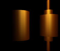
Demo 8 Extrusion and LOD
Click here to view Demo 8 in a new window
When viewing this example, move in closer to the cylinder, and watch what happens to it. Now move away again. In this next example, The LOD (Level Of Detail) node is used to select between the cylinder node used to draw an object when further away, and extrusion node to show greater detail up close. We have set the range at which this changes to 70. For the extrusion, a rectangular area is swept through a circle. The spine contains a series of points representing points along a circle through which that 30 meter tall rectange is swept. Note also the use of a more complex rotation in the transform node enclosing this all. To quickly resolve several sequential rotations into a single rotation, You may find Dizzy from Vapourtech quite useful.#VRML V2.0 utf8 # demo008.wrl Transform { rotation -1 -1 0 1.8 translation 15 5 -72 children [ LOD { range 70 level [ Transform { children [ Shape { appearance Appearance { material Material { diffuseColor 0 .8 .5 } } geometry Extrusion { creaseAngle 1.57 beginCap FALSE endCap FALSE spine [ 2.00 0.0 0.00, 1.85 0.0 0.77, 1.41 0.0 1.41, 0.77 0.0 1.85, 0.00 0.0 2.00, -0.77 0.0 1.85, -1.41 0.0 1.41, -1.85 0.0 0.77, -2.00 0.0 0.00, -1.85 0.0 -0.77, -1.41 0.0 -1.41, -0.77 0.0 -1.85, 0.00 0.0 -2.00, 0.77 0.0 -1.85, 1.41 0.0 -1.41, 1.85 0.0 -0.77, 2.00 0.0 0.00, ] crossSection [ 2 0, 2 30, 3 30, 3 0, 2 0 ] } } ] } Transform { translation 0 -15 0 children [ Shape { appearance Appearance { material Material { diffuseColor 0 .8 .5 } } geometry Cylinder { height 30 radius 5 } } ] } ] } ] }
That was a relatively simple example of the use of both LOD and extrusion nodes. The crossSection here contains only four unique points. Changing the crossSection points to represent a circle of points will result in a torus (or donut) shape. This extrusion node is very flexable and can create a variety of shapes. Here are all of the examples from above. You can save them by right clicking and then "Save Target As" etc. They do not require additional resources. Also note that it is correct to compress these files, but I have not compressed these so that they may be readily viewed in a text program without confusion. If you save them using a VRML editor you may elect to compress them at that time. demo001.wrl
demo002.wrl
demo003.wrl
demo004.wrl
demo005.wrl
demo006.wrl
demo007.wrl
demo008.wrl
